2015 Class Rules
Article I. BASIC RULE:
Section 1.01 All racing sailboats entered in Force 5 Class Association ("FFCA") events shall have been built and equipped by an authorized manufacturer. For purposes of these Class Rules, "authorized manufacturer" includes only Alcort Sailboats, AMF-Alcort Sailboats and Weeks Yacht Yard. [For sails and the Force 5 “Short Rig”, Robert J. Cullen also is an authorized manufacturer.] No additions, subtractions or alterations to authorized manufacturer-supplied boats or equipment are allowed, except in conformance with the "One-Design Guideline Principles", "Personal Modifications or Adjustments”, or “Appendices” specified in these Class Rules. All Force 5 Class-sanctioned events shall be governed by the Racing Rules of Sailing and US Sailing Prescriptions, as modified by these Class Rules and any applicable sailing instructions.
Article II. FUNDAMENTAL FAIRNESS:
Section 2.01 The rules governing sailboat racing constitute one of the most intriguing aspects of our sport because they serve dual purposes. The rules affirmatively encourage actions which promote fair and vigorous competition and, at the same time, affirmatively discourage actions which undermine such competition. The rules, moreover, are in many respects ambiguous—this ambiguity encouraging creative, good-faith interpretation and application which contributes to the appeal of sailboat racing. In contrast, a sailor who does something s/he knows is against the rules is cheating. Cheating always constitutes grounds for disqualification.
Article III. ONE-DESIGN GUIDELINE PRINCIPLES:
Section 3.01 These Class Rules are based on two (2) guidelines which are intended to maintain the Force 5 as a truly one-design racing sailboat:
(a) It is recognized that Force 5 sailors will make certain modifications to personalize their boats/equipment, and to maintain them in seaworthy and good operational condition. Such modifications shall be limited to those that do not enhance boat speed by any means that is definable, understandable or measurable.
(b) Nothing in these One-Design Guideline Principles shall be construed as authorization to repair, restore or rebuild any of the boat's standard components to competitive advantage. Any modification(s) not clearly within the letter or spirit of these guidelines or any other Class Rule shall be presumed prohibited.
Article IV. PERMISSIBLE MODIFICATIONS AND ADJUSTMENTS:
Section 4.01 Any authorized part or equipment that is not manufactured by or exclusively for an authorized manufacturer (e.g., Harken traveler system, blocks, tiller extensions, hiking straps) may be obtained from any source. Except for those items explicitly specified in the Appendices to these Class Rules, all spars, sails and blades, as well as any other standard parts or equipment manufactured by or for an authorized manufacturer, must be obtained from or through the authorized manufacturer.
Section 4.02 Mainsheets may be of any length, diameter or material.
Section 4.03 Quick- release hardware may be substituted or added to facilitate rigging (example: quick release on Outhaul, Vang block pin, etc.). A quick release mechanism for the sail clew is mandatory.
Section 4.04 Cunningham, Outhaul, Vang and Traveler control lines may be of any length, diameter or material, provided they are continuous and are used for their express purposes. The addition of knobs, knots or loops to facilitate grasping is permitted. Increasing Cunningham and outhaul purchase up to a 4:1 ratio is permitted. Blocks may be added/used for these purposes. Vang purchase may not be increased beyond 12:1
Section 4.05 Outhaul and Cunningham cleats may be of any type, and must be mounted to the wood coaming cap on the deck. Vang cleat(s) may be of any type, and must either be attached to the Vang block(s) or mounted to the wood coaming cap on the deck.
Section 4.06 Tiller length may not exceed 42" and must be of sufficient length to be captured by a preventer line running through the standard holes in rear deck lip. When the Rudder is mounted to the boat, the Tiller must pass under the preventer line, which shall not permit the tiller/rudder to rotate more than 70 degrees from centerline. Tiller Extensions may be of any length, diameter or size, and may be attached in any manner, provided they function solely as a tiller extension. Tiller Extensions may be adjustable in length.
Section 4.07 A maximum of two (2) compasses and one (1) count-down/count-up Timer may be mounted to the boat, provided such mountings are watertight. Dial card compasses may be of any type (e.g., 360 degree card, tactical card). Digital (electronic) bearing display compasses are permitted. Digital bearing display compasses also may incorporate a count-down/count-up timer, but may not have the capacity to compile bearing information (i.e. bearing memory) or to display lift/header information. No GPS-capable device of any kind (including cell/smart phones) may be carried aboard a boat that is either racing or intending to race. Electronic speed measuring devices are prohibited. Except in an emergency situation, no electronic communications may be sent or received once a skipper has launched his/her boat.
Section 4.08 Single blocks may be attached to the Traveler carriage rings (port and starboard) to reduce traveler control line friction. The manufacturer-supplied Traveler track may be replaced with an alternate design of similar function.
Section 4.09 (a) Inspection ports may be installed, but must be watertight and remain closed while racing. Foam flotation may be removed for the installation of inspection ports only as incidental and absolutely necessary. For each such installation it is recommended that a one gallon cubitainer be installed and inflated inside the hull to restore the lost buoyancy.
Section 4.10 Except as noted in 4.09, no flotation/foam may be permanently removed from inside the hull for any reason. Any internal flotation that must be detached (or temporarily removed) to make interior hull repairs must be replaced (i.e. securely re-bonded to the interior hull/deck in its original location) after the repair is completed.
Section 4.11 There are no restrictions on the type, quality or smoothness of finishes applied to the Daggerboard or Rudder. Daggerboard and Rudder blades may be covered/finished with any type of paint, coating, resin or resin/cloth combination so long as the finished blade(s) conform(s) to the specifications in Article V. Reinforced foam core Daggerboards and Rudder blades manufactured by Weeks Yacht Yard are presumed to conform to Article V specifications, as are composite mahogany core Daggerboards and Rudder blades manufactured by Weeks Yacht Yard.
Section 4.12 There are no restrictions on the type or number of wind indicators or telltales. Window telltales are permitted.
Section 4.13 Block(s) may be attached to the tack grommet to minimize wear on the Cunningham control line and/or increase purchase. This(ese) block(s) may be located either above or below the boom, but it may not be used to increase Cunningham purchase beyond the 4:1 ratio permitted in Section 4.04.
Section 4.14 The Daggerboard Trunk may be sanded, filled and smoothed. The Daggerboard Trunk may be modified to protect the board from wear/reduce water splash, provided that the material used does not project below the hull and that such modification cannot be used to create a jibing board.
Section 4.15 Mainsheet blocks may be of any type or configuration, provided overall system purchase of 4:1 is not increased. Mainsheet blocks may be moved to any location within the track on the boom.
Section 4.16 Mainsheet and Traveler cleats of any type may be mounted on wooden backing plates on either side of the cockpit in addition to the manufacturer-supplied traveler cam cleats.
Section 4.17 A "JC" preventer (boom control shock cord) may be installed with a block attached to the bow handle. The addition of cleats for this preventer is prohibited.
Section 4.18 A plug or stopper may be substituted for the manufacturer-supplied Automatic Bailer cap.
Section 4.19 Port and starboard hiking straps are permitted in lieu of the standard single center-mounted strap. Dual hiking straps must utilize the existing thwart attachment, but an additional eyestrap (no cleat) may be installed on the rear cockpit wall to facilitate dual hiking strap attachment or hiking strap adjustment, provided the installation is watertight and is at least 4" below the cockpit lip. Hiking straps may be held up with shock cord, and a third eyestrap may be installed above the manufacturer-installed eyestrap for this purpose, provided the installation is watertight and is at least 4" below the cockpit lip. Hiking straps may be covered with padding.
Section 4.20 The Rudder may be attached to the Gudgeon Bracket with a bolt or pin in lieu of the manufacturer-supplied spring/pin device. Spacers may be added to the Tiller attachment bolt between the Rudder head and the Tiller straps.
Section 4.21 Reinforcing hose clamps/safety lines may be attached to the Traveler car, gooseneck fitting and Outhaul track.
Section 4.22 Hiking pants of any type are permitted.
Section 4.23 Equipment may be substituted in conformance with Class-approved manufacturer updates.
Section 4.24 A skipper may race with a crew in any event, provided the skipper sails with crew in each race of the event.
Article V. SPECIFICATIONS:
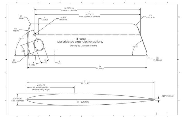
Section 5.01 DAGGERBOARD:
(a) The Daggerboard must be a manufacturer-supplied foil, the base construction of which shall be either a single solid piece of mahogany or reinforced foam core epoxy.
(b) The Daggerboard shall conform to the following dimensions:
(I) LENGTH: 44'/4" +'/2" (1 12.4CM _+ 1.25CM)
(II) WIDTH: 113/4" +'/4" (29.8CM + .64CM)
(III) THICKNESS: I AND 1/16" + 1/16" (2.7CM + .16CM) AT THE LINE OF MAXIMUM CHORD. THE LINE OF MAXIMUM CHORD SHALL BE 4 AND 3/8" (11.1CM) FROM THE LEADING EDGE.
(c) 3. The following radii shall be considered standard:
(I) BOARD TOP: 18" (45.7CM)
(II) TOP FORWARD CORNER: 1" (2.5 4CM) BOTTOM FORWARD CORNER: 6" (15.24CM)
(III) BOTTOM AFT CORNER: I" (2.54CM)
(IV) TOP AFT CORNER: 3" (7.62CM)
(V) HAND HOLE: 4" (10.2CM)
(d) The Daggerboard stopper pin location may not be changed, and shall be on a line parallel to the bottom edge, 39" + 1/4" from the bottom edge and 4" + 1/4" aft of the leading edge.
(e) Fairing of the leading and trailing edges is permitted. The leading edge may be faired within 1/2" (1.25cm) of the forward edge; the trailing edge may be faired within 2" (5cm) of the rear edge. The trailing edge must have a minimum thickness of 1/8" (.32cm).
(f) The bottom edge shall make a 20 degree angle to a line drawn perpendicular to the leading and trailing edges, and shall not be rounded side-to-side.
(g) Reinforced foam core Daggerboards and composite mahogany core Daggerboards manufactured by Weeks Yacht Yard are presumed compliant with Section 5.01.
Section 5.02 RUDDER:
(a) The Rudder must be a manufacturer-supplied blade, the base construction of which shall be either a single solid piece of mahogany or reinforced foam core epoxy.
(b) The Rudder shall conform to the following dimensions:
(I) LENGTH: 35'/2" + 1/2" (90.2CM + 1.25CM)
(II) WIDTH: 9'/2" + 1/4" (24.1CM + .64CM)
(III) THICKNESS: 7/8" + 1/16" (2.2CM + .16CM)
(c) The following radii shall be considered standard:
(I) BOTTOM FORWARD CORNER: 5" (12.7CM) BOTTOM AFT CORNER: 1/4" (1.9CM)
(d) The sides shall be flat and parallel, and may be tapered in the outer 13/4" (3.2cm)
(e) Reinforced foam core and composite mahogany core Rudder blades manufactured by Weeks Yacht Yard are presumed compliant with Section 5.01.
Section 5.03 SAILS
(a) Sails shall be manufactured only by an authorized manufacturer, and shall bear the Class insignia.
(b) Sails shall not be re-cut or re-sized. Defective sails must be corrected by an authorized manufacturer. Damaged sails may be repaired by any sailmaker, provided the repair does not re-shape or re-size the sail.
(c) Tapered battens are permitted.
(d) Sail numbers assigned by the Force 5 Class Association must appear on the sail at all times while racing. Sail numbers must be at least ten (10) inches (25.4cm) in height and must contrast with the sail color. Outline-only numbers are prohibited.
(e) Sail numbers shall be located as follows: the starboard numbers shall be applied one (1) inch (2.5cm) above the seam between the two lower battens and the first number shall be two inches (5cm) from the leech; the port numbers shall be applied two (2) inches (5cm) below, and directly in line with, the starboard numbers. Sail numbers applied in accordance with pre-1989 Class Rules are allowed, but all numbers applied after January 1, 1989 must conform to Section 5.03 (e) specifications.
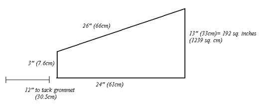
(f) Sail Windows are permitted and encouraged, subject to the following restrictions: (1) the window must be either rectangular or trapezoidal in shape; (2) the total viewing area may not exceed 202 square inches (1303 sq. cm); (3) no window edge may exceed 50 inches (127cm) in length; and (5) no part of any window seam may be less than one (1) inch (2.5cm) from a foot seam, batten pocket, the tack patch or luff sleeve seam.
(g) Diagram (recommended sail window shape/dimensions):
Article VI. SPECIFIC PROHIBITIONS:
Section 6.01 Any sail alteration except for the specific purposes of repair or adding a window or window telltales in accordance with these Class Rules.
Section 6.02 "Magic Boxes" or equivalent; lever Vangs.
Section 6.03 Use of more than one (1) hull or two (2) sails per regatta without special permission from the Race Committee. Significant hull or sail damage constitutes sufficient grounds to receive such permission.
Section 6.04 A competitor in the Full Rig (FR) division may drop down to a Short Rig (and move back up to FR) at any time during a regatta provided both sails have the same number and that all sail changes are made ashore. A competitor so doing will be scored in the Full Rig division with no time or any other handicap adjustments; i.e., boat-for-boat.
Article VII. VARIATIONS:
Section 7.01 Any variation from "standard" not covered by these Class Rules shall be presumed prohibited unless: (1) ruled compliant by the Chief Measurer (or the Chief Measurer's duly authorized proxy), subject to appeal to the Executive Council; or (2) approved by vote of the Executive Council in accordance with the provisions of the Force 5 Class Association Constitution. Rulings of the Class measurer shall be deemed controlling during the pendency of any appeal to the Executive Council.
Article VIII. PERSONAL SAFETY:
Section 8.01 U.S. Coast Guard-approved personal flotation devices must be carried on board at all times while racing (NOTE: non-Coast Guard-approved “buoyancy aids” do not satisfy this requirement). While the Force 5 Class strongly encourages sailors to wear Coast Guard-approved personal flotation devices at all times while sailing, these devices must be worn whenever the sailing instructions or the Race Committee so indicate(s).
Section 8.02 A bow line (painter) not less than 12 feet long and ¼ inch in diameter shall be attached to the bow handle at all times while racing.
Section 8.03 Weight devices of any kind are strictly prohibited.
Appendix A:
Appendix B:
|
Daggerboard Fairing Measurements |
||
|
Distance aft of the leading edge |
DB surface measured from the fore-and-aft centerline |
Daggerboard Thickness |
|
0.000 |
0.000 |
0.000 |
|
0.063 |
0.089 |
0.179 |
|
0.125 |
0.126 |
0.252 |
|
0.250 |
0.177 |
0.354 |
|
0.500 |
0.246 |
0.492 |
|
0.750 |
0.297 |
0.594 |
|
1.000 |
0.338 |
0.676 |
|
1.250 |
0.372 |
0.744 |
|
1.500 |
0.400 |
0.800 |
|
1.750 |
0.425 |
0.850 |
|
2.000 |
0.446 |
0.892 |
|
2.250 |
0.465 |
0.930 |
|
2.500 |
0.480 |
0.960 |
|
2.750 |
0.493 |
0.986 |
|
3.000 |
0.504 |
1.080 |
|
3.250 |
0.514 |
1.028 |
|
3.500 |
0.520 |
1.040 |
|
3.750 |
0.526 |
1.052 |
|
4.000 |
0.529 |
1.058 |
|
4.250 |
0.531 |
1.062 |
|
4.375 |
0.531 |
1.062 |
|
4.500 |
0.531 |
1.062 |
|
4.750 |
0.530 |
1.060 |
|
5.000 |
0.527 |
1.054 |
|
5.250 |
0.523 |
1.046 |
|
5.500 |
0.519 |
1.038 |
|
5.750 |
0.513 |
1.026 |
|
6.000 |
0.507 |
1.014 |
|
6.250 |
0.499 |
0.998 |
|
6.500 |
0.491 |
0.982 |
|
6.750 |
0.481 |
0.962 |
|
7.000 |
0.471 |
0.942 |
|
7.250 |
0.459 |
0.908 |
|
7.500 |
0.447 |
0.894 |
|
7.750 |
0.433 |
0.866 |
|
8.000 |
0.418 |
0.836 |
|
8.250 |
0.403 |
0.806 |
|
8.500 |
0.386 |
0.772 |
|
8.750 |
0.367 |
0.734 |
|
9.000 |
0.348 |
0.696 |
|
9.250 |
0.327 |
0.654 |
|
9.500 |
0.305 |
0.610 |
|
9.750 |
0.281 |
0.562 |
|
10.000 |
0.255 |
0.510 |
|
10.250 |
0.228 |
0.456 |
|
10.500 |
0.199 |
0.398 |
|
10.750 |
0.172 |
0.344 |
|
11.000 |
0.145 |
0.290 |
|
11.250 |
0.118 |
0.236 |
|
11.500 |
0.091 |
0.182 |
|
11.750 |
0.064 |
0.128 |
|
|
|
|
|
Notes: |
|
|
|
A width of 11.75" was used b/c many trunks do not accept a max width (ie, 12") DB |
||
|
For a "max-thickness" DB of 1 1/8" multiply the values in Columns C&D by 1.058 |
||
|
The profile described above is just one of a very large number of possible profiles that would have the proper max thickness at the proper location. |
||
Appendix C:
The following third-party parts and equipment have been approved by the FFCA Executive Council for use in all Force 5 racing events:
- boom based on the Dwyer DM2 section of the same length as the original Kenyon spar
- DIY or third-party daggerboards that conform in all respects to the requirements of Section 5.01 and Appendix A of these Rules
- gooseneck pins with maximum diameter of ½”
- mast sections that conform to the original specs and dimensions
- replacement bailers that fit in the original cockpit floor hole
- aluminum tapered mast collars
- any boom end fittings that do not alter any provisions of the Class Rules
- You are here:
-
Force 5 Class Home Page

-
Class Info
- Class Rules